Monday, August 20, 2012

Sail Pivot Bearing Machining

Revised:  9/02/2012          Subject to Revisions


The first part selected for machining is the Sail Panel Pivot Bearing.  One bearing is located at top and bottom of the sail panel to enable the sail panel to rotate freely.  The bearing accepts a rounded pivot shaft end located at either end of the sail panel assembly.   The round end of the pivot fits loosely inside the bearing with clearance to keep the sides of the shaft from contacting the bearing.  The ball end of the sail panel pivot rests on a cone shape inside the bearing.

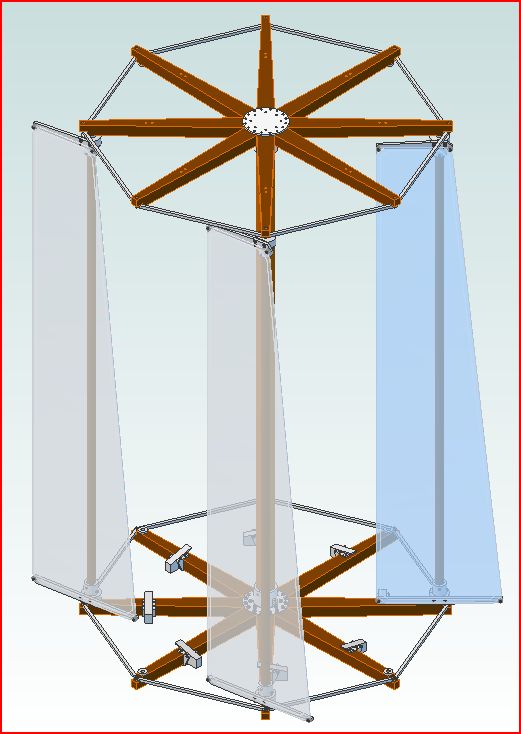
Finished Part Design Isometric

The pivot bearing has a large diameter shoulder portion that lies on top of the wood radial arm.  A short shaft portion is press fit into a hole near the end of the radial arm.  The hole in the top of the bearing holds and supports a pivot pin protruding from the bottom or top of the sail panel.  The pivot has a rounded end that contacts the bottom of the pivot bearing.  The pivot fits loosely in the hole allowing the sail panel to freely rotate with limited friction.

Piece of raw 3/8" diameter 6061-T6 aluminum rod stock

Sixteen pivot bearings are needed, one each near the end of each radial arm located at the bottom and top of each of the eight sail panels.  The bearings are fabricated from a 3/8" diameter rod of 6061-T6 aluminum.  Later, they may be made of other metals if necessary such as brass or steel depending on how well the bearings and sail panel pivots work with each other. 


Before installing the raw stock, a dead center is installed in the headstock taper collet and the normal cutting tool tip aligned to the center.  The cross slide axis (x axis) of the CNC controller is then set to zero.


Aligning Cutter Point to Dead Center 
 
CNC Controller Screen - X Axis Set to Zero
 
A length of 3/8" aluminum rod at least 1" long is used to make the pivot bearing. The rod will fit through the headstock center hole so the rod can be much longer to facilitate making a number of parts in series.

 
Long piece of rod stock being fed through hole in headstock
 
The first step is to face off the end to make it square with the lathe.  Only enough material is removed to make the end flat and even.

 
Facing Cut CAD Isometric
A normal cutting tool is then placed in contact with the cut-off face and the feed (y axis) of the CNC controller set to zero. 

The diameter is then reduced to 0.360" for a distance of 0.300" from the cut face.

 
Top Diameter Cut CAD Isometric

The diameter of the end is reduced to 0.200" for a feed depth of 0.150" completing the mounting shank cut.  

 
Shank Cut CAD Isometric
After cutting a chamfer of ~ 0.010" is trimmed from the face end to facilitate installation of the pivot bearing into the wood radial arm.

Part Being Run on Lathe Using CNC Program

The next step is to use the cut-off tool and separate the pivot bearing part from the stock at a distance slightly greater than 0.100" from the end of the 0.200" cut.  At this point the cut-off part would be set aside and another part made. 

 
Cut-Off CAD Isometric
A total of 16 pivot bearings are needed.  The author will add a rear cut-off tool to the Sherline lathe and program the part fabrication using the CNC controller.  One program will be used to cut the part as described above including the cut-off operation.  The author will then move a new portion of rod out from the center of the 3-jaw chuck into contact with the cutting tool.  The cutting tool will then be used to remove a new face and the entire process repeated except that only the feed (y-axis) will be set to zero for the next run of the CNC program.
 
 
First Three Pivot Bearings Run With CNC Program
 
A CNC program was written in G-Code language commonly used for machine tools.  The program performs all cutting steps except the first facing cut and at the moment the cutoff step. 
 
Portion of CNC Program to Make Sail Panel Pivot Bearing
 
Once the 16 parts are made (and probably a spare or two) the stock rod will be removed from the lathe.  Then each of the pivot bearings will now be inserted into the 3-jaw chuck by the small diameter section. 

Cut-Off Part CAD Isometric
The tail stock of the lathe will have a Jacobs chuck installed and a center drill installed.  Each of the pivot bearings will be center drilled a short distance to prepare to drill each pivot bearing. 

After center drilling, a pilot drill such as 3/32" will be used to initially drill a 0.180" deep hole in each of the pivot bearings.  The reason for doing all parts is that the set-up and alignment will require significant time while mounting each pivot bearing in the chuck will take less time and is gauged by the tips of the chuck fingers. 

 
#29 (0.136") Drill Hole CAD Isometric
Finally a #29 (0.136") drill will be installed in the tailstock chuck, aligned for the cut depth and each part drilled the same 0.180" depth. 

After drilling each part a manual chamfer of ~ 0.01" will be made to facilitate insertion of the sail panel pivot pins later.
 
0.01" Top Chamfer CAD Isometric


Completed Part CAD Isometric
The completed part isometric from the top view is shown above.  The bottom of the hole is a 135 degree cone set by the end of the drill bit.


Building Pivot Bearings in Quantity

After creating the G-Code program the author decided to incorporate a rear mount cut-off tool and holder on the cross slide along with the normal cutting tool.  The two tools are on opposite sides of the lathe cross slide approximately equal distant from the center and nearly opposite one another.  This allows the pivot bearing part to be built from first cut through cut-off automatically using the CNC program.
 
Once the new tool arrived and was mounted, the G-Code program was modified to include the cut-off procedure at the end and automatic alignment of the cutting tool to support placement of the next portion of stock rod material.  The program modification included the use of parameters that support quick modifications based on the position of the cutting tools as well as a control parameter to support diameter calibration based on the first part made.
 
With those modifications to the lathe and G-Code program twenty-one new parts were made with much improved accuracy.  The critical diameter of the portion that inserts into the wood radial arm was now controlled to 0.2000 to 0.2005 inches, a very tight tolerance.   These tight tolerance parts should now be able to be press fit into suitable diameter holes in the arms. 
 
Sherline Lathe With Two Cutting Tools On Cross-Slide
 
In the above photo the normal cutting tool is nearer the bottom while the cut-off tool is above.  Both tools move in the X axis (vertical in photo) together.  They are separated sufficiently to provide room for the work being turned.  The photo was taken as the G-Code program was operating and the first cuts being made with the normal cutting tool.
 
 
View of Cutting Operation on Lathe While Smaller Diameter Cuts Were Being Made
 
 
The smaller diameter cut to 0.200 inches required a total of nine passes removing 0.020 in. per pass for 1-7 and 0.010 for 8 and 9.  The outer diameter of the bearing is 0.360 in and slightly smaller than the stock bar.  This shot was also taken during a CNC run.
 
Small Diameter Cut On Final Pass
 
 
Part of the Sail Panel Pivot Bearings Being Turned
 
A total of twenty-one bearings were ultimately made.  Eight are shown above part way through the  part fabrication series. 
 
Five Set-Up Parts and Calibration Part
 
Five unusable parts were built in the process of proofing the program and lathe set-up procedures.  The lack of a rear cut-off tool on the cross-slide required that for each part the normal tool holder had to be removed and the regular cut-off tool holder installed in it's place.  This necessitated a re-alignment of the normal tool holder when it was returned to the cross slide for the next part. 
 
The multiple calibration procedures resulted in poor tolerances for the parts, running up to several thousandths of an inch despite great care.  The main difficulty is that no good reference point exists that supports better than several mils definition.  It is very, very difficult to align to the dead center used to locate the center of rotation of the lathe.
 
The addition of the rear cut-off tool means that both tool holders remain fixed in location and accurate compensation for any slight position errors can be incorporated in the G-Code program.  This is done by cutting a test part, measuring it accurately, determining the error and plugging the error value into the program.  The error is canceled out numerically by the program placing cutting tool very accurately for subsequent parts.
 
Example Accuracy Exhibited After Numerical Compensation In G-Code Program
 
Most of the parts made using numerical compensation in G-Code were within 0.0005 in of target value.  The photo above shows an example part made to target value.  The calipers used are accurate to 0.0005 in and read to the nearest 0.0005 in.  The combined error is about 0.001 in.  The parts made are expected to be within a one mil tolerance.
 
 Example Measurement Showing 03605 Readout
 
The parts all measured to within 0.001 in worst case and mostly better than 0.0005 in.  Many measured exact target value.  The numerical compensation method in G-Code works very well.  Since most movements of the lathe are fully automatic the fabrication process went rapidly.  The only manual operations were to adjust the turning rpm and position the stock bar for the next part.  The G-Code program stops and displays a message for the operator indicating what step to take before resuming the program.
 
Twenty-One Accurate and Six Set-Up Parts Along Side the Lathe 
 
After the part run was completed the above photo shows the collection of good parts in groups of three on the right and set-up parts on the left.
 
Bottle of Partially Completed Pivot Bearings on Print
 
The above photo shows a bottle of the the partially finished parts laying on the drawing.  The drawing was an output of the 3D design program - Alibre Pro.  Each of the parts will need to have the large diameter portion trimmed to correct thickness and the hole drilled.  These operations will also be done on the lathe.  They are relatively simple operations and will likely be done manually rather than using G-Code.
 
 Close-Up View of Partially Finished Bearings
The large diameter portion will be trimmed to a controlled thickness and have a hole drilled part way through the part to a controlled depth.  The drill will form a cone at the bottom of the hole which will become the bearing surface.   Each of these steps will be performed on the lathe.  A simple facing operation will trim the thickness while a tailstock mounted set of drill bits of increasing diameter will be used to drill the hole in steps.

Each part will be chucked in contact with the surface of the chuck fingers being held by the small diameter. A facing cut relative to the chuck finger surfaces will be made to trim the part. Each part will be mounted and face cut with a common cross-slide position so that all parts match.

A flat file was used to make a small radius on the top edge to eliminate any sharpness.

A flat file was used to radius top edge


Close Up of Part With Top Radius
 
 
 Part Before Applying Flat File to Make Radius
 

Drilling begins with a center drill to located the middle of the diameter.   This is done using the tailstock.  The center drill leaves a starting dimple in the center of the face cut.

 Center Drill Used To Make Accurate Center Pilot Hole
 
Center Drill Held in Jacobs Chuck Attached to Tailstock
 
 
Center Drilling Underway
 
After the above step the smallest of a series of drills will be installed in the Sherline Mill Jacobs chuck.   The depth will be calibrated for the drill tip position.  This is done using a calibrated reference part that has a measured 0.1000" top portion thickness. 

Selected Part With Blue Marking On Bottom Has Exact 0.1000" Top Edge Thickness

Each part will be installed and drilled to the calibrated depth.  Following that a slightly larger size drill bit will be installed and the procedure repeated on each part.  A series of four drill bits of increasing size (#45 (0.082"), #38 (0.101"), #30 (0.128") and #29 (0.136") were used to reach the final hole diameter.  The depth of each bit was driven down 0.180"from the calibrated top surface.
 
Sherline Mill Driven Via CNC To 0.180" Depth

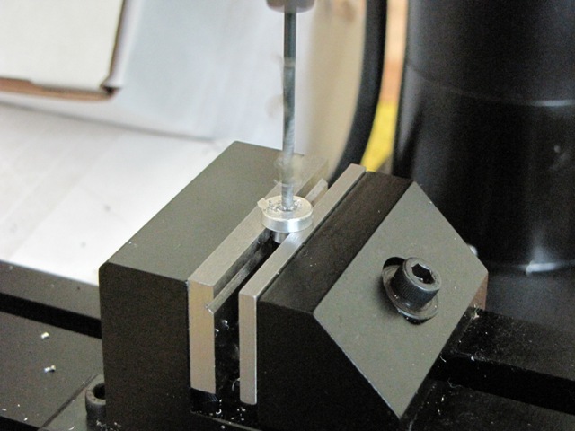
Each Part Placed in Mill Vice For Drilling

Eighteen Good Parts and Standard Thickness Part With Blue Dot On Bottom

Working with CNC G-Code for this project has expanded the author's understanding of automatic machining.  The machining of this part has greatly increased understanding of setting feed rate and spindle speeds to optimize chip formation for good cutting operation.  The use of parameters and decision steps in G-Code has improved ability to achieve tighter tolerance using measurements after machining and adjustment parameters in the program to trim final cuts.

The next part of the project will be to tackle the wood radial arms.  These will be made of red oak obtained at the local home improvement store.  The mill will probably be the major tool employed to cut part outline and bore critical holes.  A special purpose boring tool may be needed for the 0.200" holes for the sail pivot bearings just completed.  They will be mounted in a snug fit hole and glued in place. 

Another key metal part to tackle will be the limit stops.  The stops consist of two parts, one fixed and the other pivots to allow the sail panels to move freely in one direction and restricts them in the other.  The moving part is pushed down by the sail panel sliding up the ramp surface in the free direction while the panel hits the end of the ramp in the other direction and cannot move past it.  Those parts will be fabricated using the mill mainly.  The pivot for the ramp is a small machine screw.

Another metal part that may be made before the limit stops is the end braces that go between the tips of the radial arms.  These are simple square stock with a cut down interface with the next brace so they overlap.  Two overlaps meet at each radial arm tip and are held in place with a machine screw that passes through the two and the radial arm.  A nut and washer on the bottom secures the screw.

Several complicated metal parts are used on the sail panels, the top and bottom pivots and the bottom and top sail frames.  These will require a combination of lathe and mill work.

All of these parts will keep the author quite busy for the next many weeks.  Progress on this project is interrupted by efforts to build two other models mentioned in the companion blogs.

Sunday, August 5, 2012

Overall Turntable Design

Revised:  8/5/2012            Subject to Revision

The design of the overall turntable was done in order to size the key components and determine a reasonable structure that could be modelled and operate in a manner analogous to the storyline prototype.

The overall concept has previously been presented.  The turntable structure is built around two wheel assemblies, one at the bottom and another at the top held together by a central mast.  The radial arms of the wheels serve to support the sails and transmit the torque to the central hub and thence down into the waggon cabin for power takeoff.

The wheels consist of wood radial arms bolted to a central hub with spacers between the ends to form a wheel.  Just inside the tips of each arm is a bearing for a sail assembly.  The bearing allows the sail to pivot freely.


The sails are free to rotate up to a sail stop mechanism that allows the sails to freely rotate counter-clockwise but constrains the rear bottom spar to rotate only to the radial arm when rotating clockwise.  This is done to permit the sails to freely rotate into alignment with the wind on one side of the wheel while holding the sails on the other side aligned similar to the paddles on a water wheel.


The sail stop mechanisms are pivoted with a counter weight that keeps the stop tip up when the sail attempts to push past when traveling clockwise but tilts down to allow the sail bottom spar to depress the tip when traveling counter-clockwise.


The top portion of the hub on the bottom wheel holds a wood mast.  The mast is secured with bolts to prevent rotation in the hub and transmission of torque coming down from the mast top. 


At the top of the mast another wheel is mounted less the sail limit stops.  This wheel has bearings facing those on the bottom wheel.  The bottom and top wheels are identical except the top wheel does not have the sail limits mounted.


The picture above shows three of the eight sail assemblies installed between the top and bottom wheels.  The two at the left and bottom center are aligned with a wind coming at the wheel from the lower right side at a ten degree angle to the right-lower arm. 


Above all eight sail panels are installed showing how the four at the bottom and left and facing into the wind while those at the right and top are held rotated to the wind by the limit stops.  Those at the bottom and left apply no torque to rotate the wheels while those at the right and top catch the wind and apply torque to rotate the wheel counter-clockwise looking down from above the turntable.


The sail panel assembly consists of a center mast, a bottom spar with pivot, a top spar with pivot and a cloth sail panel with cord edges.  The spars are metal while the mast is wood.  The mast is held in each of the spars with bolts to transmit torque between the spars so that the limit stop at the bottom holds the entire sail panel.  The cloth sail panel is held at the four corners with bolts at the ends of the spars.  Because the leading edge of the sail panel is tapered more sail area lies behind the pivots than in front.  This causes the sail to to align the leading edge facing the into the wind unless the sail panel is constrained by the sail stop.  The pivots top and bottom fit into bearings near the tips of the wood radial arms of the wheels.  The wheels hold the sails in place with sufficient clearance to permit the sail panels to freely rotate.
The above parts define the turntable with the exception of the bottom hub and shaft that will transmit torque to the drive mechanisms below the deck.  The bottom hub will attach to the bolts holding the wood radial arms on the bottom wheel.  A threaded cap plate is used above the top wheel to provide a way to torque the upper wheel bolts.  The bottom wheel lower hub will use the bolts in a similar fashion.  The shaft and hub assembly below decks will provide support bearings and clamps to hold the turntable assembly in place while allowing it to rotate freely.

The upper deck portion of the turntable is sufficiently designed and the parts detailed to point where model parts can be fabricated.  The wood parts will be made of a hard wood such as oak while the metal parts will be made of 6061 aluminum.  The bolts will be stainless steel or other steel depending on availability.

The assembly has many, many parts to be made.  The next entries in the blog will likely discuss and illustrate results of parts fabrication.  Most of the work will use the Sherline CNC mill and CNC lathe.  Since most of the parts are replicated many times the CNC program feature will be a near necessity to limit drudgery and boredom.

The companion blog about the Wind Waggon Trek (see links on page header) can be embellished with more storyline about the expected design of the prototype and fabrication of prototype parts as model parts fabrication occurs.  Meanwhile more model design work can be done with the drive shaft, drive mechanisms and waggon box structure and later use the model design to drive the story.  An unrelated part of the storyline consists of character development and threading together various storyline actions and conflicts to make it interesting. 


Saturday, June 23, 2012

Designing the Turntable Bottom Structure

Revised: 7/6/2012          Subject to Future Revisions

The first step for the design of the model, keeping in mind the prototype considerations of the storyline of The Wind Waggon Trek blog, was to configure an eight radial arm bottom support for the sail panels.  The material for the arms is akin to red oak wood.  Each arm on the prototype will have a ten foot radius when assembled, although each piece is somewhat shorter to provide the central hole for the main mast that will be attached at the center.

Each radial arm is sized to handle the prototype sail panel applied stress.  On the model the parts will also be red oak or other hard wood suitable for cutting on the mini-mill.  A metal hub will be attached on top that also supports the main mast and another hub on bottom that connects to the support bearings and the main turntable drive shaft below.  The other end of the drive shaft will also connect to a bearing hub.  Near the ends of the radial arms there are mounting holes for the sail panel bottom bearing. 


At the hub end of each radial arm there will be three bolt holes used to attach the arm to the hub.  The extreme end of the radial arm will have a bolt hole for a metal braces that connect to the neighbor radial arms.  The ring of metal braces form a hoop that keeps the arms at a constant angle to one another.  The model parts are scaled 3/4" = 1ft.  The prototype radial arms have a 20 ft overall diameter.  The model will have a corresponding scaled size of 15" diameter.


The bolts that connect the radial arms to the metal hub will be #2-56.  At this point they will thread into a lower hub disc with matching hole positions.  The outer end bolt connecting to the metal braces connecting adjacent arms will be #0-80.  In addition to the bolts, a pocket for a 0.2" diameter bearing is located at a prototype radius of 9' which scales to 6.75" radius on the model.  Those bearings will support the sail panels and permit them to freely swivel.  The sail panel shaft diameter will be 0.125" on the model, 2" on the prototype.  The bearing will be a metal pocket with 0.01" clearance.  The end of the sail panel shaft will be tapered and rounded to provide a vertical support.  The sail panel should freely rotate on the metal to metal bearing. 


A slightly tapered main mast will mount in the center hole of the hub and connect to the center of an upper hub supporting the top set of radial arms.  The mast couples the torque from the upper sail panels to the bottom hubs.  The metal hub at the top connects together the eight top wood radial arms that look similar to those on the bottom and have essentially identical functions.  Each radial arm at either the top or bottom carries the same lateral load, one half of sail panel wind pressure.  The radial arms are strong enough to carry the lateral load.  The mast is strong enough to carry the rotational force loading of the top set of radial arms.  A shaft from the bottom hub couples the entire torque load of the sail panels down to the power take off pulley.  The bottom shaft like the upper main mast is also wood.  Both the upper main mast and lower drive shaft are pinned to the metal portion of the hubs to prevent slippage under torque loading.

The turntable will consist of many pieces:     (List subject to revision)
     Eight lower radial arms
     Eight upper radial arms
     Eight sail panels
     Sixteen sail panel bearings
     Sixteen bearing outer housing
     Sixteen bearing inner housing
     Sixteen radial arm tip brackets
     Sixteen radial arm tie rods
     Sixteen radial arm tie rod keepers
     Sixteen radial arm tie rod keeper bolts
     Upper main mast
     Lower drive shaft
     Upper top hub
     Upper bottom hub
     Lower top hub
     Lower bottom hub and bearing housing
     Lower hub bearing
     Lower hub housing
     Bottom drive shaft upper hub
     Bottom drive shaft lower hub and bearing housing
     Bottom drive shaft bearing
     Bottom drive shaft bearing housing
     Bolts for hubs to secure shafts
     Bolts for radial arms to secure arms to hubs
 

Tuesday, June 19, 2012

Rethinking the question of sail power

Revised:  7/6/2012        Subject to Revisions

The information regarding wind pressure on flat surfaces indicates that the original 16' tall by 4' wide sail panels for the prototype wind waggon would be insufficient producing less than one horsepower. Consequently, further thoughts suggest that both the turntable diameter and sail height should be increased to develop more power.


 By growing the turntable to 20' diameter and sail panel height to 30' with a width of 8' the wind pressure grows considerably. Further, with the increased diameter, more sail panels can exist. The sail bearings could perhaps be at a diameter of 18'. The bearings would lie in a circle whose circumference is 56.5'. The sail panel bearings lie 2/5ths of the distance from front to back of the sail or 3/5th of the distance from the back to front. Two adjacent sails must clear their back sections when rotating which indicates a sail spacing of 2x3/5th or 1-1/5th or 1.2 times the width of a sail, plus clearance of about 2” or 0.2 of a foot.  Each sail provides half of the clearance or 1” or 1/10th foot.


Using the rotating clearance for sails as 1-1/5th the sail width and a bearing site diameter of 56.5' a couple of possible sail widths and count occur. With eight sail panels around the spacing of the bearings is 7.0625'. This spacing must represent 1.2 of the panel width which comes to 5.8854'. By deducting 2/10ths of a foot for clearance each sail panel must be 1/10' less or 5.78'. Round this to 5.75' to make the overall dimension more rounded.


With eight panels, four would be capturing wind power at the same time. They would be at angles of 22.5, 67.5, 112.5 and 157.5 degrees. The wind pressure on those panels are proportional to the sine of the angles times the pressure on a 90 degree panel which is (0.38268 + 0.92388) x2 = 2.613. The pressure on a 90 degree full panel of 5.78' x 30' (173.4 sq ft) for a 20 mph wind is 1.6 psf x 173.4 sq ft = 277.44 lbs.  The combined pressure on the four downwind panels would be 724.95 lbs.  The sail panels would be expected to move at about 10% of wind speed which is 0.1 x 88/3 = 2.933 ft/sec.  The turntable would rotate once in 19.26 seconds or 3.1 rpm.  The torque applied to the turntable shaft would be 724.95 lbs x 9' or 6,524.56 ft lbs.  Assuming the turntable shaft has a 1' circumference, in one revolution in 19.26 seconds a force of 6,524.5 lb would be applied or 338.76 ft-lb/second.  This corresponds to about 0.6159 horsepower.  The horsepower increases as the square of the wind velocity.  At a 40 mph wind the horsepower is 2.4636.   It might be a bit more than that as the turntable rotation rate will increase as well by double.   That would further increase the horsepower by a factor of 2 to 4.9247. 

Force on a sail per square foot at sea level is ~ 0.004v^2 where V is wind speed in mph.  A revised concept vehicle was devised for the story that lowered the turntable to a point a few feet above the tops of the wheels and tapered the sail panels to reduce the tipping wind force at the top of the turntable.  A design of that configuration will be pursued using the eight sail panels.


Another option might be to use the original quantity of six sail panels. For that instance adjacent bearings lie 9.4157' on centers. This space must represent nearly 1.2 of a sail panel width which comes to 7.847'. Deducting a bit for clearance and rounding suggests 7.70'.  The sail panel area would be 7.7' x 30' = 231 sq ft.  the wind force on a 90 degree panel would be 369.6 lb.   The panels would be 60 degrees apart.  The downwind side would have one panel at 90 and two at 30 degrees to the wind.  The combined force would be 2 times one panel for a total of 739.2 lbs.   Sail panel rotating speed would be the same as the previous case at 19.26 seconds per revolution.  Turntable torque would be 6,652.8 ft. lbs, about the same as previous. 


Curved sails with airfoil like shapes would increase power somewhat but complicate the design of the sail panels and would further require the use of some form of trim method aligned with the wind.  By doing his however, sails moving with and against the wind can both contribute rotational force to the turntable.  This constitutes a further radical improvement in technology and will be left for perhaps a follow-on model project.

Monday, June 18, 2012

Selecting the Model Scale

Revised: 6/18/2012                          Subject to Revision

The prototype wind waggon box in the blog story (see other blog links) is 24 feet long and 10 feet wide and some 8 feet tall.   The overall height is about 30' 10" tall including the sail turntable.  The prototype wind waggon is a fictional machine featured in a fiction blog being written by the same author as this blog.  The idea for both is develop the story and the model in parallel so that design aspects of the fictional prototype are practical features developed for the model. 

The author intends that the model be working and controlled by radio control equipment developed for model airplanes, etc.  The RC equipment would permit the model to be operated in a rear prototype manner to evaluate how well model design features operate while the model is running.  The scale for the RC model needs to be determined to provide adequate volume for both the model running gear of scale belts, pulleys, gears, levers and such, but the RC servos, receiver and batteries as well.  Modern RC servos, receivers and batteries are very small, however, it is conceivable that perhaps one or two larger size servos may be required to operate control levers in the model.

Should a scale of 1/2"=1' be used the model box would be 12" long, 5" wide and 3.5" high.  Granted there will be considerable scale mechanisms for wheel drive involved, but perhaps sufficient space would exist for several RC servos, receiver and battery.   This seems a bit tight.


An alternate that would provide more space would be to use a scale of 3/4"=1' which would result in a model 50% larger.  That would give a main box of 18" long, 7.5" wide and 6" tall, approximately.  The overall height with the sail turntable would be 23.125".   In the story the actual size has not yet been finalized, although a notional design has been presented by the lead designer.  During concept design detailing by thane wind waggon team in the story, the design will be subject to change. 

It might work best to detail the equivalent model features and then migrate those to the story so that various operational features will work both in the model and in the prototype.   In the ongoing development, the model design will pace the story line and the prototype sizes of various details will be driven by the more detailed model design being done in parallel.  The model and prototype designs will be done using Aibre 3D CAD software.  Insofar as practical, the model will be built using the same materials as the full size prototype.  The model design will be such that it can directly be scaled up to prototype size and look correct there.  Features such as parts made of various materials would be prototypical insofar as possible.

The society in the story has fairly primitive metal working capabilities, perhaps analogous to those that existed in the 16th and 17th centuries and equivalent woodworking skills.  They could not make large metal parts such as long shafts suitable for the turntable mast, but could make pulleys, gears, reinforcement hoops, short shafts, longer rods, threaded bolts, etc.  They could work in various metals such as brass, aluminum, iron or steel, etc.  They could also make castings up to several feet in size and machine those parts with drills, mills and planing tools.  For wood they could make parts quite long up to near tree length, bind, glue, mortise, join, drill, chisel and many other operations.

The model will take these capabilities and limitations into account and design the larger structures as combinations of wood and metal taking best advantage of each.  The wood for the model will probably be largely oak or other similar hard wood.  The metal will largely be aluminum.

First Parts
The first parts to be considered are the rotating sails and turntable.  Both in developing the model and the prototype in the story those are drivers to the balance of the design.  

Sails
The sail in particular is revolutionary.  It is a rigid structure built on a largely wooden frame covered with sail cloth.  The direction given the development team in the story is that the structure be built in sections so that broken parts can be replaced from spares if need be and that the canvas sails be attached with hooks or bolts so it too can be replaced.  Each such sail is some 16' tall and perhaps 4' wide.  It is mounted on bearings so it can freely turn.  No ropes or other devices are used to move the sail.  It is more like a lightweight panel than a canvas sail typical to a ship.   On the model each sail panel would be 12" tall and 3" wide.  The trick will be to design the wood frame for suitable strength on the prototype and design it to be held together with bolts for the model.  The sail cloth will probably be some fine weave cloth such as silk for the model, or perhaps some other material such as nylon or rayon.  The trick for the cloth will be to devise suitable reinforced holding points for bolt or hook attachments.
A wind pressure calculator on the web indicates that the pressure on a prototype wind sail of 64 square feet orthogonal to a wind would be 0.56 pounds per square foot (psf) with a 20 mph wind (35.84 pounds total) and 2.24 psf with a 40 mph wind (143.36 pounds total), 5.02 psf at 60 mph (321.28 pounds total), 8.9 psf at 80 mph (569.6 pounds total) and 13.96 psf at 100 mph (893 pounds total).
 
Turntable
The turntable is a complex structure holding six sail panels evenly spaced around their mounting diameter.  The vertical forces on the turntable are not large considering that the sails are relatively light weight.  The larger forces to be reckoned with are the wind forces that push the sail panels to rotate the turntable.  The problem is to adequately couple the sail panel side forces to the turntable shaft. 


As was pointed out in the story, the lead designer estimated that the each sail panel on the prototype could experience about 893 pounds of side force coupled half and half to the upper and lower sail panel bearings that attache the panels to the turntable radial arms.  Each radial arm would experience 446.5 pounds of side force at a point about 4 feet from the turntable shaft, a moment arm force of 1786 pounds applied towards rotating the turntable shaft.  Each radial arm would need to be strongly anchored at the shaft end and braced so that it would not twist out of alignment with the shaft.

The primary problem with the radial arms is to safely couple the high rotational torque to the shaft and keep all radial arms in proper position.  Those radial arms are about 5' long and made of hardwood.  The shaft is also hardwood.  Coupling the high force torque through two pieces of oak at right angles is the problem.  The design will most likely need to use metal joints to do so such that the wood radial arms couple their force into a metal channel that in turn couples the force through a right angle channel around the central shaft.  The channels that contain the wood parts would use bolts to keep the wood parts firmly in place.  The portion around the central shaft would be a large piece of metal that channels top and bottom for the turntable shaft and six radian channel for the radial arms.

The long 16' central shaft of the turntable between the bottom and top of the sail panels carries half of the overall sail force.  In the story the lead designer indicated that the expected forces would be 1.35 times that of one panel at 4' radius or 2411 foot-pounds torque force.  The central shaft below the turntable going down into the box where the power take-off would exist would need to handle  the entire 2.7 times the force of one panel or 4822 foot-pounds torque force.  Additionally, the turntable shaft would need to handle perhaps 75% of panel force as side bending force of about 904 pounds as the sails will not travel around at wind speed so as in a ship sail considerable side force will be applied to the central shaft as well.   All the above figures are for the very unusual case of a 100 mph wind, an extreme case in a severe storm.  The lead designer is very conservative and wants the design to hold up even in a severe storm.  As the story evolves, a sort of sail throttle will evolve that will free the sails to rotate most of the time and only rotate them at an angle to the wind in order to deal with strong winds.

A much larger problem is that the rotating sail panels will likely only be useful with fairly brisk winds of 20 to 40 mph.  Twenty mph winds only provide a miserly force of  96.8 pounds at the 4' sail panel radius or 387 pounds torque total for instance.  Depending on the drive ratio this may be sufficient.  The estimate made in the story is that the turntable rotates at 10 to 20 revolutions per minute which it probably could do with no load.  Loading depends on the drive ratio and overall load due to waggon weight and whether going uphill, etc.   During story evolution a drive transmission of pulley ratios is contemplated to permit driving with various wind speeds, waggon weights and driving conditions. 

Waggon weight and wheel drag conditions have not been determined and as the design evolves the ratio of transmission pulleys may need to be revised to permit waggon progress with relatively low wind velocities.  It may also be necessary to increase panel size or even resort to two turntables or possibly to revise the sail panel arrangements on the turntables.  An alternate configuration using airfoil shapes with flaps to orient the airfoils relative to the wind permits four or more airfoils to pull together increasing the number of elements that extract wind power.  In the interests of simulating a new revolutionary design in the story, flat sail panels were selected.

It is expected that the turntable shaft below the top of the waggon box will extend down to the inside lower deck at the bottom of the box.  Bearings at the box top and bottom will need to hold the turntable shaft in position vertically while allowing the shaft to freely rotate while sustaining the side forces due to the wind.  The waggon box will need to be reinforced to bear the forces applied.  At the bottom bearing plate below the bottom of the waggon box a large pulley wheel will be used to couple the turntable rotational torque to the main transmission assembly.  

The design will attempt to located all of the drive transmission below the waggon box bottom inside a covered area between the drive wheels.  At this point the main drive pulley is expected to rotate from 10 to 20 times per minute on the prototype.  Based on the lead designers calculations, the force applied to the drive transmission pulley will be of between 64.5 foot-pounds per second available to drive the prototype vehicle in a 20 mph wind.  That is not much power.  One hp is 550 ft-lb / sec, so the effective motive power is 0.117 hp.  Not very practical if the calculations are correct. 

The model sail panel is 0.0039 time the area of the prototype and have a surface area of about 1/4 square foot.  A twenty mph wind would apply 0.56 x 1/4 = 0.14 pounds force for one orthogonal sail panel.  The three panels absorbing wind power would be 2.7 times that or 0.378 pounds.  The sail force would act at a radius of 3" which is 1/4 ft.  The expected torque level would be ~ 0.0945 ft-lbs.  If the turntable were to rotate ~ 10 times per minute the effective power would be 0.01575 ft-lb/sec.  That is 0.000029 hp.   That seems incredibly small so the vehicle would move very slowly.   It seems that their needs to be much more sail area to produce a reasonable amount of horsepower.